
23 October 2026 — Embedded-systems engineering. Texas Instruments made CAN XL a practical purchasing decision in August when it introduced the TCAN6062 CAN SIC XL transceiver. The part is significant, but the next question for a machine builder is less glamorous: how do we prove the complete node and wiring work? A 20 Mbit/s figure in a device specification is not an acceptance test for a production machine.
We previously covered the TCAN6062 product launch and its implications. This is the follow-on engineering work: eight tests for a controlled laboratory prototype before anyone signs off a CAN XL design or touches a running machine. These are proposed engineering acceptance checks, not evidence that CANS or a customer has qualified a particular product.
1. Verify the CAN XL controller, not just the transceiver
A physical-layer transceiver cannot turn an ordinary CAN FD controller into a CAN XL protocol controller. Check the microcontroller or communications IP against ISO 11898-1:2024 and the intended CAN XL configuration. Verify controller firmware, drivers, receive filtering, diagnostics and the test analyser. A pin-compatible transceiver swap is not a protocol upgrade.
For the TI TCAN6062, confirm the actual controller supplies the mode-signalling waveform expected on TXD, including pulse-width modulation (PWM) for FAST operation. The product specifies operation in SIC, FAST TX and FAST RX modes under ISO 11898-2:2024 Annex A. Document controller and transceiver revisions together, not as two unrelated approved components.
Evidence: Bill of materials, controller and transceiver datasheets, firmware revision, valid CAN XL frame captures and a reproducible test fixture.
2. Capture arbitration-to-FAST-mode transitions
CAN XL retains CAN-style arbitration while providing a higher-speed data phase. CAN in Automation explains that CAN SIC XL transceivers switch from their arbitration behaviour into a dedicated FAST transmit or receive mode for the XL data phase. That transition is part of the design’s timing budget, not something to assume is invisible.
Use a suitable oscilloscope, differential probe and protocol analyser to correlate TXD, RXD, CAN_H/CAN_L and decoded frames. Verify valid transitions in both directions at the intended nominal and data-phase rates. Test long and short payloads, back-to-back traffic, idle recovery and the slowest and fastest clock combinations allowed by the design. Consult the actual vendor’s timing limits rather than copying a generic 20 Mbit/s target.
Evidence: Timestamped waveforms and decoded traces demonstrating correct switching, valid sampling and complete frame reception at the specified operating extremes.
3. Test the actual harness and node topology
A tidy demonstration board tells little about a distributed machine with long cable routes, drop leads, connectors, variable ground potentials and drives switching nearby. Record actual bus length, stub lengths, termination, cable impedance, node loading and connector arrangement. Establish a low-speed baseline before increasing data-phase speed.
Build the worst permitted topology, not merely the shortest laboratory cable. Measure ringing, overshoot, settling, eye quality where appropriate, and error counters across the fastest supported data phase. CAN SIC technology can help control ringing, but it cannot repeal transmission-line physics. Avoid publishing one universal cable-length promise without a topology and acceptance test behind it.
Evidence: Wiring drawing, termination measurement, scope captures, error-free operating envelope, and documented pass/fail limits for each approved harness variant.
4. Demonstrate mixed-network behaviour explicitly
TI specifies CAN, CAN FD, CAN SIC and CAN XL physical-layer operation for the TCAN6062. Bosch and CAN in Automation also discuss migration and mixed CAN FD/CAN XL networks. Nevertheless, physical-layer support is not proof that every older protocol controller will accept every new frame or that arbitrary combinations of nodes will interoperate.
Test each approved mixture of controller type, firmware, transceiver and analyser. Exercise Classical CAN and CAN FD traffic where the configured CAN XL controller supports it. Test CAN XL data frames only in a configuration designed to handle them, with well-defined gateways or segments where required. Record error frames, bus-off behaviour and the response of legacy nodes. Do not connect a new XL transmitter to a production CAN FD network merely to see what happens.
Evidence: Supported-matrix table covering frame formats, active nodes, bit rates, observed error states and gateway rules.
5. Measure latency under realistic traffic, not only peak throughput
CAN XL permits payloads as large as 2,048 bytes, compared with 64 bytes for CAN FD. This helps transport richer diagnostics and configuration data, but a long occupied data phase still affects scheduling. A maximum transceiver bit rate does not guarantee application-level response time, particularly when nodes share the bus and upper-layer fragmentation, retries and gateways are involved.
Generate the worst realistic combination: cyclic control messages, asynchronous faults, diagnostic bursts, firmware-transfer loads and restarts. Measure end-to-end latency distribution, deadline misses, controller queue depth, actual bus loading and recovery time. Include high-priority messages that arrive during longer transfers. Keep measurement at the application boundary as well as the physical bus.
Evidence: A recorded traffic profile and a signed latency/deadline report against the machine’s own requirements, including peak loads rather than average figures alone.
6. Exercise power, standby and fault recovery
The TCAN6062 documentation specifies standby, remote wake-up, undervoltage response, thermal protection, TXD dominant timeout and passive behaviour when unpowered. Verify what those protections actually mean in the assembled product. They are device features, not automatic proof of a safe machine design.
Test cold start, hot plug where permitted, 24 V system disturbances at the power input, MCU brownout, transceiver supply interruptions, stuck TXD, bus disconnection and cable reconnection. Check that receive logic does not report stale valid process information and that the firmware leaves bus-off or fault states in a defined manner. If a communications timeout affects actuation, retain the independently engineered safety and control functions outside this bench test.
Evidence: A fault-injection matrix showing observable node states, operator indication, recovery conditions and confirmation that no unintended outputs were commanded.
7. Qualify electrical robustness for the installation
Industrial environments introduce electrostatic discharge, fast transients, conducted and radiated interference, common-mode disturbances and ground offset. TI lists IEC ESD measures and ±58 V bus-fault protection for the transceiver, but those figures do not certify an assembled product against its required EMC and electrical-safety standards.
Define applicable IEC 61000-series immunity tests and any sector-specific product standard with the compliance team. Include cable shield/bonding decisions, surge paths, ground reference, common-mode range, supply filtering and PCB layout. Exercise communications during disturbance, not just after it. Document temporary performance degradation and correct recovery under the agreed criteria.
Evidence: Approved electrical test plan, qualified laboratory results where required, and repeatable bus-error and recovery records.
8. Prove diagnostics, maintenance and rollback
A new network becomes a maintenance obligation on the day it is commissioned. Confirm that service personnel can identify node hardware/firmware versions, inspect receive and transmit errors, distinguish missing equipment from wrong configuration and recover from a failed update. Check firmware-update integrity, log timestamps, retention and how a replaced node is commissioned.
Rehearse an incompatible firmware release and a deliberate rollback on a test fixture. Confirm that tools used by field engineers actually decode the configured CAN XL traffic; a CAN FD-only USB interface should not be described as a CAN XL analyser. Set explicit criteria for when the existing CAN FD design remains the better answer.
Evidence: Revision-controlled commissioning procedure, diagnostic screenshot/log set, restoration test and a traceable sign-off by embedded, electrical, controls and maintenance representatives.
A practical release gate
The output should be a bounded hardware acceptance report: a supported-node matrix, approved topology, waveforms, stress and EMC results, worst-case traffic measurements, fault-injection logs, firmware revision, known limitations and an owner for any remaining exceptions. Maintain a clean separation between a laboratory protocol test, a machine integration test and a live safety validation. Passing the first does not certify the next two.
For existing installations, the default may be to keep CAN FD and introduce a gateway or a separately qualified CAN XL segment. That is not resistance to progress; it is recognising where the remaining engineering value actually lies.
CANS engineering support
CANS works across embedded electronics and industrial communications, architecture and engineering consultancy, and CAN/CAN FD diagnostic interfaces. Interface and analyser selection must be checked against the exact CAN XL controller and protocol requirements: existing CAN FD hardware should not be assumed to provide CAN XL decode capability.
For a hardware qualification plan, gateway design or industrial-network retrofit, contact CANS or send the engineering team a WhatsApp enquiry.
Technical sources and image rights
- Texas Instruments, TCAN6062 product announcement, 12 August 2026.
- Texas Instruments, TCAN6062 technical product information and datasheet (CAN XL SIC/FAST modes, electrical limits and fault behaviour).
- CAN in Automation, CAN XL protocol overview (arbitration, data phase and mode transitions).
- CAN in Automation, physical-layer options (bit rates, wiring and CAN SIC XL hardware).
- Bosch, CAN XL implementation and protocol compatibility (ISO 11898-1 and migration considerations).
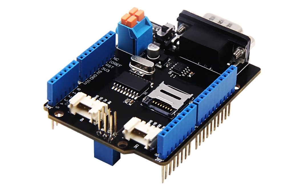
Featured photograph: CAN BUS Shield V2 (2017), by Seeed Wiki, Wikimedia Commons source and attribution, CC BY-SA 4.0. Illustrative conventional CAN development board, not a TCAN6062 or CAN XL evaluation board and not CANS project equipment. The photograph appears as the featured image only, not duplicated within the article.

Recent Comments