
20 October 2026 | CANS engineering analysis. Siemens and NVIDIA have put some useful detail behind the phrase “AI-driven factory”. Their 19 October 2026 announcement from Siemens’ Electronics Factory in Erlangen describes two concrete applications: preparing PCB inspection before physical boards exist, and testing AI-generated production plans against a factory digital twin before changing the live schedule.
That is considerably more interesting to an automation engineer than another demonstration of a chatbot describing a production line. The machinery still needs to build a conforming product, and the factory still needs to know which order, revision, materials and inspection evidence belong to it.
What Siemens and NVIDIA actually announced
At Erlangen, which manufactures power electronics and automation equipment, Siemens says digital-twin-derived, photorealistic images are being used to prepare vision inspection for new printed circuit board assemblies. The stated aim is to avoid waiting for first physical prototypes before configuring and training an inspection system. NVIDIA Cosmos is identified as the technology generating realistic inspection training data.
Siemens reports that this virtual preparation can reduce engineering effort by up to 85% and shorten time-to-market by up to 40% for the relevant PCB workflow. Separately, it says an AI agent can propose production schedules, compare capacity and material constraints, and validate options in a plant digital twin. The company says that approach can enable cost savings of up to 20%. These are Siemens-reported, application-specific potential gains, not independently verified savings available to every factory. The source does not supply a universal baseline, confidence interval or guaranteed return on investment.
Importantly, the planning system is described as generating alternatives and showing their KPI implications to planners, with digital-twin validation before implementation. That distinction matters: recommendation and physical execution are different authorities.
PCB inspection: synthetic images are a head start, not the acceptance test
Preparing an AOI or other machine-vision recipe from PCB design data has obvious appeal. If the electrical design, assembly drawing, bill of materials, component geometry and revision are trustworthy, simulation can produce plausible component views long before the first batch reaches the conveyor.
The hard work begins when the real board arrives. Solder fillets, component tolerance, silkscreen variation, flux residue, shadows, lens distortion and lighting drift can all differ from the simulated image. A model trained on convincing synthetic images may still miss a subtle physical defect, or reject good assemblies at an unacceptable rate. A photorealistic picture is not automatically a statistically representative defect population.
For a production deployment, the sensible validation sequence is to lock the correct PCB and assembly revisions, build a traceable sample set from physical boards, and challenge the algorithm with genuine defects, rework and permitted process variation. Record false-accept and false-reject rates by defect class, not merely a headline “accuracy” number. Put recipe changes, model versions, image acquisition settings and operator overrides under change control. Inspection evidence needs a serial number or lot, an unambiguous timestamp and a route into the manufacturing execution system (MES).
A particularly awkward failure mode is an apparently good AI verdict attached to the wrong board revision. Traceability prevents that embarrassment more reliably than another percentage point on a model benchmark.
Factory scheduling: the digital twin must reflect the actual constraints
An agent can generate schedules quickly. Whether they are useful depends on its understanding of the plant. A nominal line rate does not describe changeover time, available fixtures, material shelf life, maintenance windows, operator qualification, rework loops or upstream bottlenecks. None of those constraints disappears because the planning interface looks intelligent.
For digital-twin-assisted scheduling, engineers should test scenarios against recorded production behaviour: order release, work-in-progress, machine states, planned and unplanned stops, material availability and actual cycle-time distributions. Plant models need a version and an owner. Otherwise the optimiser may produce a beautiful schedule for a factory that no longer exists.
The OEE data and the MES event history have to agree on what constitutes an operating machine, a good part and an attributable loss. Shift changes, rework and blocked/starved conditions are frequent sources of discrepancy. An agent cannot repair a badly defined production event by optimising it faster.
Where the control boundary belongs
Industrial AI should initially sit above deterministic machine control. Read trustworthy PLC and SCADA signals through appropriately configured interfaces, correlate them with order and quality records, and give planners an auditable proposal. A human-approved schedule can then pass through the normal production-order and machine interlock workflows. Do not let a general-purpose model write directly to hazardous-motion outputs, bypass machine permissives or modify safety logic.
When connecting the model to live systems, a practical interface contract specifies tag meanings and units, source timestamps, expected update rates, quality flags, loss-of-connection behaviour and replay handling. Edge buffering helps when a line must continue operating through a network or MES outage. Interfaces such as OPC UA or controlled message delivery are useful, but the protocol alone does not make data semantically correct or authorise remote control.
OT network segmentation, least-privilege identities and a tested recovery path remain relevant; see NIST’s Guide to Operational Technology (OT) Security, SP 800-82 Revision 3. For models themselves, NIST’s AI Risk Management Framework provides a useful basis for testing, evaluation, monitoring and accountability. Neither substitutes for a machinery-specific risk assessment.
A workable starting point for an existing factory
Most manufacturers in Malaysia and Singapore do not need to reproduce the whole Erlangen architecture. Pick a measurable problem on one line: preparing AOI recipes for frequent PCB revisions, tracing quality rejects to lot and machine conditions, or comparing proposed schedules against reliable WIP and capacity data. Establish an as-is baseline, collect the minimum trustworthy data, and run the proposed model in shadow mode before it can affect production. Measure engineering hours, genuine defect escape, rework, schedule adherence and downtime with the same definitions before and after.
For plants with mixed PLCs, legacy equipment and separate ERP/MES systems, the first integration task is often making machine events and production records agree. CANS’ PLC and SCADA engineering, AI vision inspection, CANiS integration middleware and CansNEXUS digital-twin platform are relevant engineering areas to assess. Capability is not evidence of a completed deployment or guaranteed outcome.
Siemens’ announcement is significant because it connects design information, inspection preparation and factory scheduling to a working production environment. The next test for everyone else is not whether a digital twin looks realistic on a screen. It is whether the versioned model, live data and actual machine agree when production is under pressure.
Discuss an inspection, MES or digital-twin integration requirement: contact CANS or send an engineering enquiry on WhatsApp.
Source notes and image credit
The 19 October figures and Erlangen application descriptions come from Siemens’ official 19 October 2026 press release; the Erlangen press event hub supplies its setting. Engineering caveats and implementation recommendations above are CANS’ analysis, not claims of deployment by CANS.
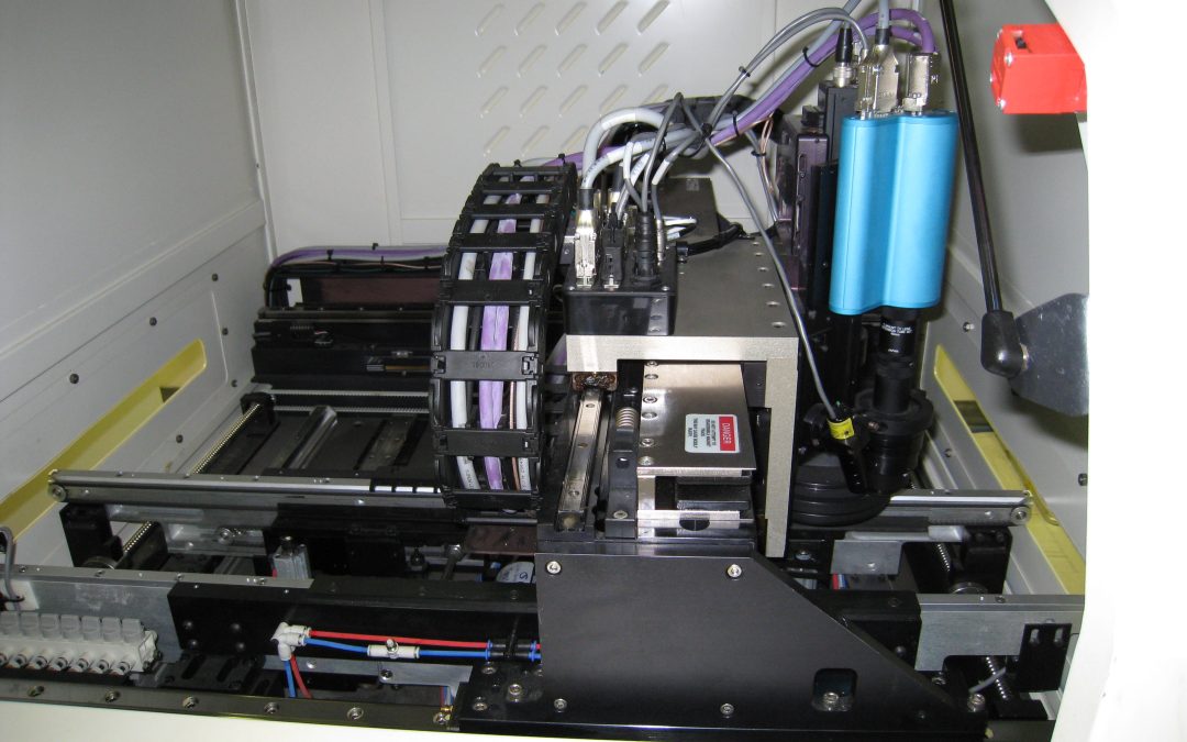
Featured photograph: inspection camera inside a solder-paste inspection machine, photographed in 2008 by Nelatan / Wikimedia Commons, CC BY-SA 3.0. Illustrative image; not Siemens’ Erlangen factory or a 2026 system. No modifications to the source photograph are claimed.

Recent Comments