
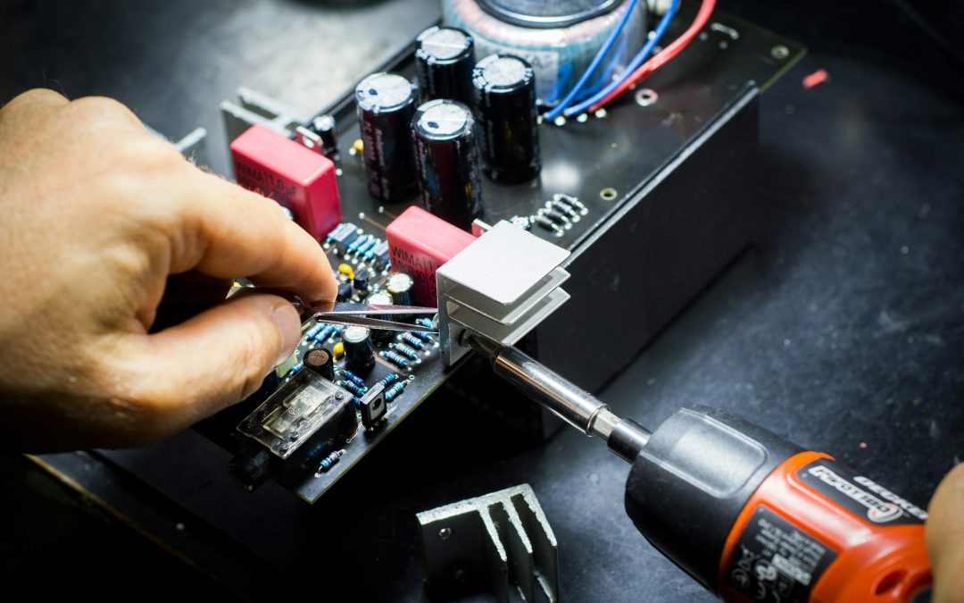
An overhead camera can show that a connector was placed in a housing. It cannot prove that a locking screw reached its specified torque. Both may appear in a digital work instruction as one assembly step, but they require different evidence. That distinction matters when AI vision is used to check whether an operator followed a standard operating procedure (SOP).
Manual assembly is an awkward target for conventional machine vision. Hands hide components, parts arrive in different orientations, and a good operator may complete the same job in several legitimate ways. Vision can still be useful, particularly for presence, orientation and sequence checks. The trick is to make the system record what it actually observed rather than awarding a pass to an action it merely inferred.
Why this is moving beyond demonstrations
There have been some concrete developments in 2026. On 12 May, Bosch Rexroth and Arkite announced a collaboration combining industrial workstations with digital operator guidance and real-time step validation. Cognex introduced its NVIDIA Jetson-powered In-Sight 6900 Vision Controller on 28 April, giving machine builders more local processing capacity for demanding inspection workloads. Rockwell Automation’s 9 July VisionAI update added VisionStream for learning product characteristics from live production data and flagging anomalies.
These are different products serving different tasks. An anomaly detector trained on images of good assemblies is not automatically an action-recognition system. Likewise, a workstation guidance platform does not prove the tightening force of a tool unless that measurement is integrated. I would be wary of specifications that blur those distinctions.
Decide what counts as evidence
For a small electronics assembly station, consider five possible checks:
| Assembly event | Evidence suitable for release | What a camera alone cannot establish |
|---|---|---|
| Correct component selected | Part marking, tray position or barcode linked to the work order | Electrical rating when visually identical variants exist |
| Component seated in housing | Visible alignment, orientation and final presence in a defined region | Hidden mating depth or internal contact condition |
| Fastener tightened | Calibrated tool result and torque/angle record tied to that fastener | Actual tightening torque from a screwdriver motion |
| Cable routed correctly | Visible route, clip engagement and final cable position | Continuity or insulation integrity |
| Functional test completed | Tester result carrying unit identity, limits and pass/fail | Electrical performance from appearance alone |
Vision is one evidence source, not the complete proof of assembly. A camera can catch a missing clip and reduce rework. For the torque point, it should correlate the visible operation with the electric screwdriver’s result. For the finished assembly, it may need to combine camera checks with a test fixture or PLC-controlled end-of-line measurement.
Represent the job as a sequence of events
It is tempting to process video into an overall percentage labelled ‘SOP compliance’. That is not especially useful when a supervisor must decide whether one specific unit can move to the next station. A more defensible record contains the work-order or serial number, recipe and revision, station ID, expected step, observed result, timestamp, evidence reference, model version and disposition.
The disposition should have at least four states: PASS, FAIL, NOT OBSERVED and MANUAL REVIEW. A covered camera view, dropped frame or model timeout must not silently become PASS. The rule is especially important during rework, when a correct repair may happen out of the original sequence.
Unit identity should come from the station transaction, such as a barcode scan or fixture acknowledgement, not from the camera guessing which product is on the bench. Start and end each observation window with deterministic station events. Otherwise a good image from the previous unit can be attached to the next serial number. That kind of error is difficult to spot after production has moved on.
Occlusion is the normal condition, not an exception
For manual work, hands occupy much of the useful camera view. Glossy housings, changing gloves, operator posture and tools moving through the scene add variability. Installing two cameras may help, but can also increase calibration, synchronisation and maintenance effort. Try a controlled view of the final assembly state before investing heavily in continuous gesture recognition.
A short proof-of-concept should deliberately include awkward samples: left- and right-handed operators, large and small gloves, partial occlusion, similar-looking wrong parts, rework, a missing step and acceptable alternative sequences. Reserve these samples for independent acceptance testing. If all the test images came from the same lighting setup and the same two operators as training, the accuracy number is not very persuasive.
Record false accepts separately from false rejects. A false accept lets a bad assembly proceed; a false reject interrupts a good operator. The acceptable rates depend on the consequence of the defect and the availability of downstream inspection. Also measure the proportion of cycles ending in NOT OBSERVED. A model that rejects uncertain frames may look excellent on the remaining images while providing very little actual coverage.
Keep control authority where it belongs
My preferred architecture separates observation, production disposition and machine safety. Cameras and an edge computer produce bounded inspection events. A station controller or PLC owns the cycle state, verifies that the event belongs to the active unit and decides whether to permit the next normal process step. The MES or manufacturing record stores the outcome and evidence needed for traceability. Safety-rated interlocks, emergency stops and hazardous-motion protection stay in their validated safety system; a general-purpose AI model is not a substitute.
For integration, the useful interface is often a small set of structured events rather than a continuous video stream. OPC UA can be appropriate for exposing camera or edge-inspection results to industrial software; IDS, for example, demonstrates AI-capable cameras using OPC UA and the machine-vision companion specification. The PLC may instead use a conventional digital handshake when the application only needs a request, result, timeout and reset. Choose the boundary the existing control system can reliably maintain.
Do not quote just the inference time when sizing the workstation. Include camera exposure, transfer, frame queue, preprocessing, inference, result transmission and PLC scan timing. Under worst-case CPU or GPU loading, a queue may grow or frames may be discarded. A bounded timeout with a clear operator review path is generally more useful than a nominal ’20 ms AI response’ without an end-to-end timing budget.
Traceability should be designed before storing video
There is a large difference between storing an event and recording a person continuously. For production quality, a unit-linked verdict, a cropped image of the relevant assembly feature and the calibrated tool/test records may be enough. If longer video is genuinely required for investigation, define access control, retention and deletion rules first. Operator privacy and Malaysian or Singaporean personal-data obligations must be assessed against the actual use, especially if faces, identifiable work patterns or performance metrics are collected.
Version the SOP, camera calibration, recipe and model together. A PASS generated under last month’s fixture position may not be valid after a jig modification. Keep a deliberate change-control path, sampled revalidation and a way to review disputed results without concealing manual overrides.
What I would test on one workstation
Start with a step that has a clear visual endpoint: a connector seated, a protective cover installed or the correct component in a known position. Keep the existing independent functional tests. Establish the real defect classes with production and quality engineers, collect representative good and bad examples, then run the vision station in shadow mode without controlling release. Compare each result with verified ground truth over different shifts and operators.
Only after the false-accept, false-reject, NOT OBSERVED and cycle-time results are acceptable would I connect the disposition to the PLC’s normal advance logic. Document what happens if the camera is offline, the model is unavailable or the operator needs authorised rework. No system should create a permanent stop merely because the model cannot see past someone’s hand.
For manufacturers in Malaysia and Singapore, the potential value is not a camera that watches people. It is a credible assembly record attached to each unit, with fewer escaped omissions and a shorter investigation when a defect is found. The hard part is integrating evidence from vision, tools, testers and machine control without pretending that one AI verdict proves everything.
CANS works on industrial automation, embedded systems and machine-data integration. For a machine-vision retrofit, new assembly station or traceability interface, send an engineering enquiry or WhatsApp CANS on +60 12-295 9602.
References
- Bosch Rexroth and Arkite collaboration on intelligent manual-assembly workstations, 12 May 2026.
- Cognex, In-Sight 6900 Vision Controller launch, 28 April 2026.
- Rockwell Automation, FactoryTalk VisionAI VisionStream and VisionLink, 9 July 2026.
- IDS Imaging, OPC UA and AI vision at the field level, technical demonstration.
Recent Comments